| Step |
Where can I find that? |
Action |
Details
|
| general prep (once a week) |
Vault |
Sweep, ground Flare, turn on equipment in the technical area |
|
| 0 |
prep for FELIX |
Check interleave settings are on FELIX, also check Timers, especially B8 |
S1=1000 us, width = 2 us, S2 = 11000 us, W= 9010us, S3 = 5000us, W=17000us, S4=1us, W=49000us
|
| 1 |
on Flare interface computer |
If FLARE solenoids are off, switch them on. |
|
| 2 |
Main panel |
Switch on all 5 FELIX & Felice buttons |
|
|

|
| Turn the key from “standby†to “runâ€. Switch on all 5 main buttons for FELIX (assuming all machines have been turned on).
|
|
| 3 |
FELIX User Station (wnd ) |
Select the correct user station |
|
|

|
| In the window “FELIX User Stationâ€, choose the user station and if 25 MHz is should be turned on.
|
|
| Select 25 MHz or 1 GHz
|
| Open vacuum system.
|
| 4 |
FELIX_dump_line_L2 (wnd) |
Find or Load a previous dump-line setting for E-range |
|
|

|
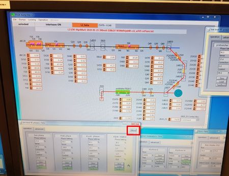
| In the window “FELIX_dump_line_L2â€, find a previous (and most recent) setting for the same beam energy / rep rate. (1) Open “Fileâ€, “Find settingâ€, “loadâ€. The suitable file name should then appear (2). Then “unlock†the panel.
|
|
| 5 |
low-level RF phases (wnd) |
Find or Load the same setting in low-level RF phases |
|
|
|
| In the window “low level RF phases > Felixâ€, right-click the menu box, “openâ€, and “load†the corresponding 25 MHz setting. This must be identical to the file loaded earlier.
|
|
| 6 |
Magneetslingercircuit (wnd) |
Change current to match 2B20-25 |
|
|
|
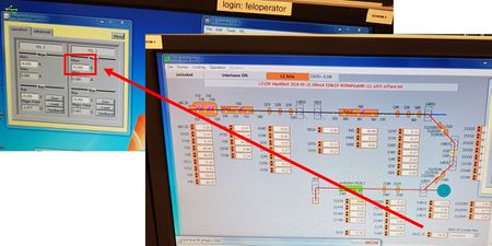
| In the window “Magneetslingercircuitâ€, change the current to match the value shown in “2B20_25â€.
|
|
| 7 |
Gun > Felix (wnd) |
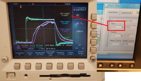
Change gun bias to ~170.5 V @ 25 MHz or ~80 V @ 1 GHz. |
|
|
|
| In the window “Gun > Felixâ€, change the gun bias to ï¾76 V (for 1GHz) and ï¾170.5V (for 25MHz). This value is often noted in the filename…
|
|
| 8 |
HPRF.vi (wnd) |
Check the file has correctly loaded in the HPRF window. Set values to match the yellow values |
|
|

|
| In the window “HPRF.viâ€, double-check the file has been loaded. Set the boxes to the loaded yellow target values. Then, switch on the button “3GHz RF timing onâ€.
|
|
| 9 |
Main panel |
Switch the “3GHz RF timing on†button on |
|
| 10 |
low level RF phases (wnd) |
Set klystron modulators to target values (from file name). |
|
|

|
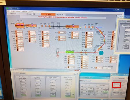
| Set the klystron modulators so they reach the target value (specified in the file name, with the line “E38k1V W39k6Vâ€). Set the step to about 4k – 5k, and the base to the corresponding required level.
|
|
| 11 |
Felix Timers (wnd) |
Check timer S1 = 2µs and rep. rate = 1Hz. |
|
|

|
| In “Felix timersâ€, ensure (1) timer S1 is 2us, and (2) frequency divider is 10 (so 1Hz output)..
|
|
| 12 |
OC Control (wnd) |
Insert BS, and align cavity mirrors. Watch 2S21, align downstream. Watch 2S41, align upstream. Remove BS. |
|
|
|
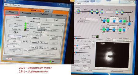
| Insert the beam splitter, and align the HeNe through the cavity mirrors. Watch “2S21†and adjust the downstream mirror. Watch “2S41â€, and adjust the upstream mirror. Remove the beam splitter.
|
|
| 13 |
Main panel |
Press ‘GUN RF timing on’. |
|
| 14 |
Felix dump line L2 (wnd) |
Optimize e- path. Align with indicator. PM10 = SX10. PM20 = SX11. PM30 = SX30* (fault with blue, align 1 square below indicator). PM40 = SX40. PM50 = SX55. PM60 = SX70. Slowly ramp to ï¾10µs / 10Hz, ensure all e- are dumped. |
|
|

|
Optimize the electron path. From the window "bo_gui_pm_main", press the "PM" button, and match-up the trace with the indicator on the left-hand scope. To do this, open the window "FELIX dump line L2", and adjust the following elements: PM- 10, 20, 30*, 40, 50, 60, 2PM30**. SX- 10, 11, 30, 40, 55, 70, 2Q2040, 2Q2050, 2Q2060. Yellow is the x-axis, blue is the y-axis.
- align the blue channel one square below indicator
- optimize to highest light value (yellow)
|
|
| 15 |
Felix Timers (wnd) |
Check timer S1 = 2µs and rep. rate = 1Hz. Open vacuum system. |
|
|

|
| In “Felix timersâ€, ensure (1) timer S1 is 2us, and (2) frequency divider is 10 (so 1Hz output)..
|
|
| 16 |
low level RF phases (wnd ) |
Fine-tune low level RF phases. Once done, press ‘zero’, ‘load’, and ‘feedback on’ in all. |
|
|

|
| In the window “Low level RF phases > Felixâ€, fine-tune the low-level RF phases. Set to zero if close to 10, and press “load†-> “feedback†on.
|
|
| 17 |
At diagnostic station |
switch amplifier to x1 (@1GHz) or x10 (@25MHz). |
|
| 18 |
Gun / prebuncher Felix (wnd) |
Adjust gun bias to achieve 360mV @25MHz / 200mV @1GHz (yellow curve on scope) |
|
|
|
| In the window “Gun > Felixâ€, change “bias†to achieve ï¾360mV (Ch1 on scope).
|
|
| 19 |
OC control Felix (wnd ) |
Find cavity zero. Set ‘dt_CLdetuning’ to zero, and adjust “DT_CLzero†close to an unstable state. Then, reset ‘dt_CLdetuning’ to 1.8. |
|
|

|
| Find cavity zero. In the window “OC Control FELIXâ€, set “dt_CL detuning†to 0, and change “DT_CL zero†in factors of 10. Optimize the height of Channel 1 only (it should be close to the unstable state). Then reset “DT_Cldetuning†to 1-2.
|
|
| 20 |
uc-flx-gui (wnd) |
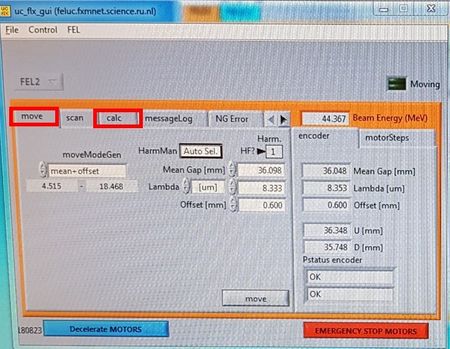
Calibrate λ. Go to calc, and set lambda to correct live value. |
|
|
|
| Calibrate the wavelength. In the window “uc_flx_guiâ€, go to calc, and set the wavelength to the correct live value. Go to the diagnostic station, and flip the amplifier to x10.
|
|


